About two weeks ago before calling the day a night, I have challenged my Chinese friend (Nicole, 你好!) to play a minigame called “Jump” (跳一跳) with me. It used to be a popular game that is integrated into the WeChat messaging app, with one simple goal: touch the screen just long enough to charge up a jump to reach the next platform. You fall off, you lose. Well, I lost. I lost every time. So instead of going to bed that night, I started working on “a solution” that would ultimately mutate into a robot that uses image recognition to finally make me win the game.
Yes, this story is about winning — about winning the challenge I’ve posed to myself that night. I drew up a quick sketch on paper of how the solution might work and what parts are needed. But first, let me introduce the game:
There isn’t much more to it. So, here’s what I came up with:
Connect an Arduino Nano to a servo with a rubber tip stuck to the horn, and connect the Arduino to my laptop for control.
Somehow analyze a video stream of the game on my laptop to determine the player’s position {$p$} and the target coordinates {$t$}.
Determine the jump distance {$d$} between the two coordinates using the Pythagorean theorem. Multiply {$d$} by some factor {$f$} to calculate the touch duration {$t$} (i.e. how long the servo needs to press onto the phone’s screen, assuming jump distance scales linearly), and add a constant time {$c$} that accounts for the servo’s response delay:
{$$ t = \sqrt{(p_x - t_x)^2 + (p_y - t_y)^2} \times f + c $$}
Issue control commands to the Arduino and perform a tap on the phone with the correct duration to time the next jump accurately.
Repeat until victorious.

Simple enough? Let’s put it together. Source is on Github.
Circuit Setup
I got myself a breadboard and plugged everything together:
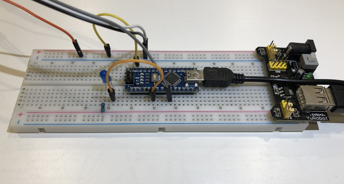
Plop an Arduino Nano into the middle of the breadboard and connect it to the laptop through Mini USB (and wish it were Micro USB).
Connect the breadboard power supply to the laptop via USB. Top rails are set to 3V, bottom rails are set to 5V.
Connect the servo’s control wire to port
D7and correctly plug the+/-wires into the 3V top rail.(Optionally) set up a basic LED circuit with a 100Ω resistor controlled through port
D3that will indicate when the jump is being performed.Connect Arduino
GNDto the top ground rail.Plug an extra wire into the top ground rail that will later be connected to the rubber tip. This seems to help the phone detect the touch correctly.
Servo Setup
This is the solution I came up with for holding the phone and the servo:
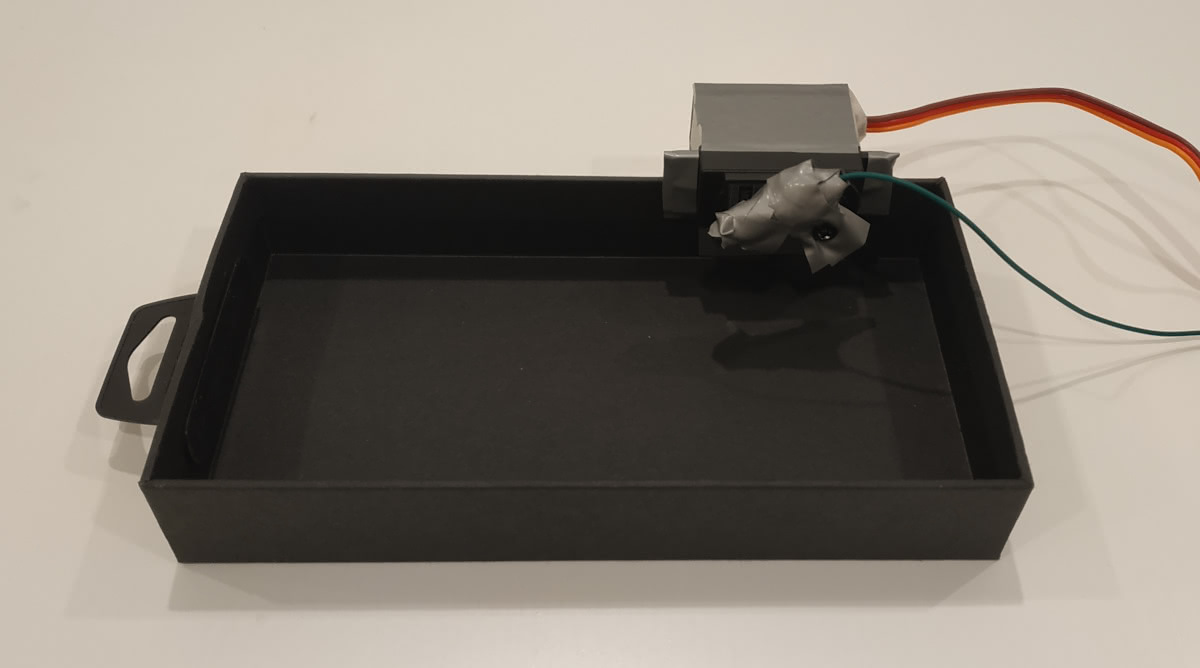
Find a cardboard box of roughly your phone’s size.
Somehow duct-tape a rubber tip onto your servo’s horn at a 90° angle. I used a crocodile clip to achieve this. Make sure the tip is connected to the grounded wire mentioned before to give it some more capacitance. I’m not entirely sure why it seems to work when it’s grounded. Please enlighten me on Twitter or in the comments down below.
Cut a slit into the bottom right side of the box and insert the servo.
Use more duct-tape to make everything not fall apart. I placed some Lego bricks under the servo for additional support.
Note: consider using a servo with a fast reaction time (mine was really slow). Also try to mount the rubber tip in such a way so that it is as close to the phone’s screen as possible without touching it. This can be adjusted in code later.
Finished Build
After connecting everything up to the breadboard, this was the final result:
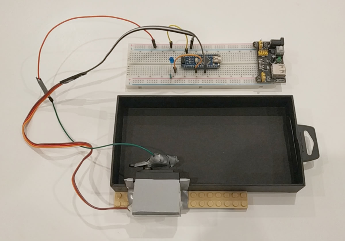
With the easy part completed, let’s dig into the fun stuff.
Programming the Arduino
If you are designing a distributed system, one of the core question to ask is “which part does what exactly”. In this case, I have decided to implement the entire control logic on the laptop and use the Arduino only for moving the rubber tip up and down. To achieve this, I am simply sending control bytes over the serial port: receiving U means go up, D means go down.
Global State
The following code snippet is all that’s needed to set up the global state:
|
Since the Arduino is a “dumb” controller, state information is essentially limited to the servo controller and a boolean flag that indicates whether the servo should be up or down.
Make sure that the pin numbers are assigned correctly depending on your build setup and adjust PITCH_UP and PITCH_DOWN angles so that the rubber tip touches your phone without crushing it.
Up/Down Controls
We’ll need two functions that move the rubber tip up/down and turn the LED on/off based on the is_down flag. Again, no magic here:
void up() { |
Setup & Loop
To set up the Arduino, we initialize serial connection for receiving commands to 9600 baud, set up the control pins, and attach the servo controller to the pin and move it to the UP position:
void setup() { |
The loop itself simply reads bytes from the serial connection (if any are available), and calls the up() or down() function accordingly:
void loop() { |
Sweet, that’s already it! Now let’s move on to the interesting part where I made things unnecessarily hard for myself — because I could.
Object Detection with OpenCV
Before objects can be detected, we have to somehow get a video stream of the phone onto the laptop for analysis. To do this, I simply placed a second phone above our contraption with the CamON Live Streaming app installed, allowing us to get a live video feed.
Now, I already hear you yell at me: why don’t you just use ADB?!
You’d be right. We could just use ADB to retrieve perfect images with no visible artifacts, distortion, or sizing issues. Oh, and hey! Since we’re using ADB, we might as well send perfectly timed touch commands to the phone directly, allowing us to completely bypass the entire build we’ve set up before. And, while we’re at it, why not just use the Android Emulator and do everything in software, or even better, interact with the server directly?
With that out of my system, let’s look at the implementation.
The Plan
Once again, straightforward plan:
Fetch the current frame from the live feed.
Do some image manipulation and analysis: resizing, cropping, blurring, edge detection, template matching, and whatever else is required to more ore less reliably determine the player position and the center of the next platform.
Calculate the touch duration using the formula I stated above.
Send
DDDD...to the Arduino to move the rubber tip down, wait for the calculated amount of time, then sendUUUU...to lift the tip back up.Repeat until victorious.
Now, I’m very well aware that step #2 is straight out of this meme:
While I won’t go into every detail, I’ll elaborate on the most important bits. Again, the source code is available on Github and questions/suggestions are very welcome.
Step 0: Quick Overview
I tried to structure the code as simple as possible. There is one global state object that contains the initial configuration, which is then being modified by the functions I have defined. The initial configuration is heavily dependent on the setup and has to be adjusted whenever anything changes. I have briefly documented what every field does in the code. The most important ones that need to be adjusted are: stream_url, serial_port, frame_margin, player_figure_scale, player_base_offset, player_window_offset, player_window_height, tap_multiplier ({$f$}), and tap_delay ({$c$}).
The program itself is divided into three threads: the first thread continuously fetches frames from the live feed, the second thread executes jumps based on the current state, and the main thread processes the frames and carries out the object detection. The main reason I have opted for Python threads is that there does not seem to be a way in OpenCV to skip frames, which lead to the program fall far behind the current frame in the live stream. While this certainly isn’t a very clean approach, it does work rather well as we’ll see later.
Step 1: Fetching a Frame
The thread fetching the frames has one job only: receive the frame and update the global state accordingly. If anything goes wrong, it terminates the program.
def read_frame_thread(): |
The cv2.VideoCapture constructor takes an URL as its argument. In my case, this was a basic mjpeg stream.
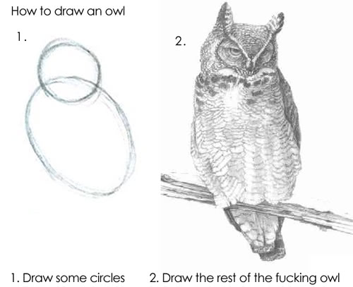
Step 2: Drawing the Rest of the Owl
Alright, now that the circles have been drawn successfully it’s time to tackle the really tricky part and start drawing the rest of the owl. The two functions, detect_player_position and detect_platform_position, each take the current frame and attempt to find the coordinates of the respective objects.
Finding the Player
Detecting the player became relatively straightforward after I have learned about the magical function called cv2.matchTemplate. The function takes the current frame and a template of the image you want it to find. In our case, this is the player. It then returns a bunch of values giving information about the location of the object:
def detect_player_position(frame): |
First, I crop the input frame (line 5) to the rough dimensions within which I expect the player to be located. This is to limit the search space: matchTemplate is extremely slow and doing this definitely helps.
Second, matchTemplate is executed (line 6) and the coordinates are then determined by minMaxLoc (line 7). In our case, max_loc contains the values we’re interested in.
Third, the player position and the player bounding box are determined based on the coordinates estimated by matchTemplate by adjusting for player size and pre-defined offsets (lines 9 and 12).
Detecting the Center of the Next Platform
Now, this one was rather challenging to say the least. This function is quite a bit longer than the rest, so I’ll break it up into separate chunks.
We’ll start by defining the function and determine the width and height of the frame:
def detect_platform_position(frame): |
Next, we’ll have to do some edge detection to figure out where the platform actually is. After a long time trying, I’ve gotten good results by first applying medianBlur to remove some of the noise by smoothing the image and then running Canny edge detection over the current frame:
frame = cv2.medianBlur(frame, 7) |
We then ‘remove’ the outer margin of the frame by painting it black to avoid the edge of the image being detected. This is basically a ‘deadzone’ around the image, which also makes positioning the camera easier.
# Remove margins. |
To narrow down the vicinity of the next platform (which is always the top-most), we limit the search space to the area between the top 1/3 of the frame and everything above the top 1/3 of the player. Additionally, we remove the player itself by painting the player’s bounding blox in black.
# Remove the top 1/3 of the screen (mainly to get rid of the score). |
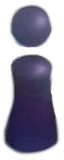
At this point, the processed frame should look similar to this:
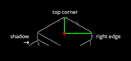
To find the center of the platform, we need to find the x-coordinate of its top-most pixel and the y-coordinate of the top-most pixel of its right edge. Note that I chose the right edge because the ‘sun’ casts shadows on the left side of objects. If we used the left edge, the shadow would interfere with the calculation.
We find the center by walking through the image, pixel-by-pixel, and adjusting the coordinates as we go:
# Try to find the top-most platform's center. |
Remember to add the offset of the top 1/3 we cropped off, and we’re done!
Step 3: Calculating the Tap Duration
Let’s recall the formula I’ve specified above and define a function that implements it:
{$$ t = \sqrt{(p_x - t_x)^2 + (p_y - t_y)^2} \times f + c $$}
Again, {$f$} is the tap duration multiplier, and {$c$} is the tap delay introduced by the servo:
def calculate_tap_duration(): |
The function takes the player and platform position tuples holding their respective coordinates from the global state and updates the tap_duration field that will be used for the next jump.
Step 4: Sending the Control Commands
To send control commands to the Arduino, we’ll first define the send_command function. Its parameter represents the byte to be sent over the serial connection: b'D' for down and b'U' for up.
def send_command(command): |
The function ‘remembers’ the most recent command that has been sent and will only print the current command (to limit debug output).
The thread actually performing the jump logic consists of a timed loop. It first waits for the inter-turn period to pass and then starts sending the b'D' command for the exact duration of the tap that has been calculated before, causing the rubber tip to be pressed onto the phone. After the jump has been ‘charged up’, the thread starts bursting the b'U' command which will raise the rubber tip again.
def perform_jump_thread(): |
The jump logic will be executed until the program ends.
Step 5: Beat my Friend
Now that this rather nefarious plan has been implemented, it was time to compare highscores with my friend. It seems that I now have a slight advantage.
Hey, It’s Actually Working!
Surprisingly, this contraption is working much better than I expected:
There are still some rough edges here and there. For example, the robot seems to struggle with very short jumps, which is the reason it failed at the end of the video. However, this could potentially be fixed by setting a minimum jump duration or by making a specific adjustment for jumps below a certain threshold — good enough!
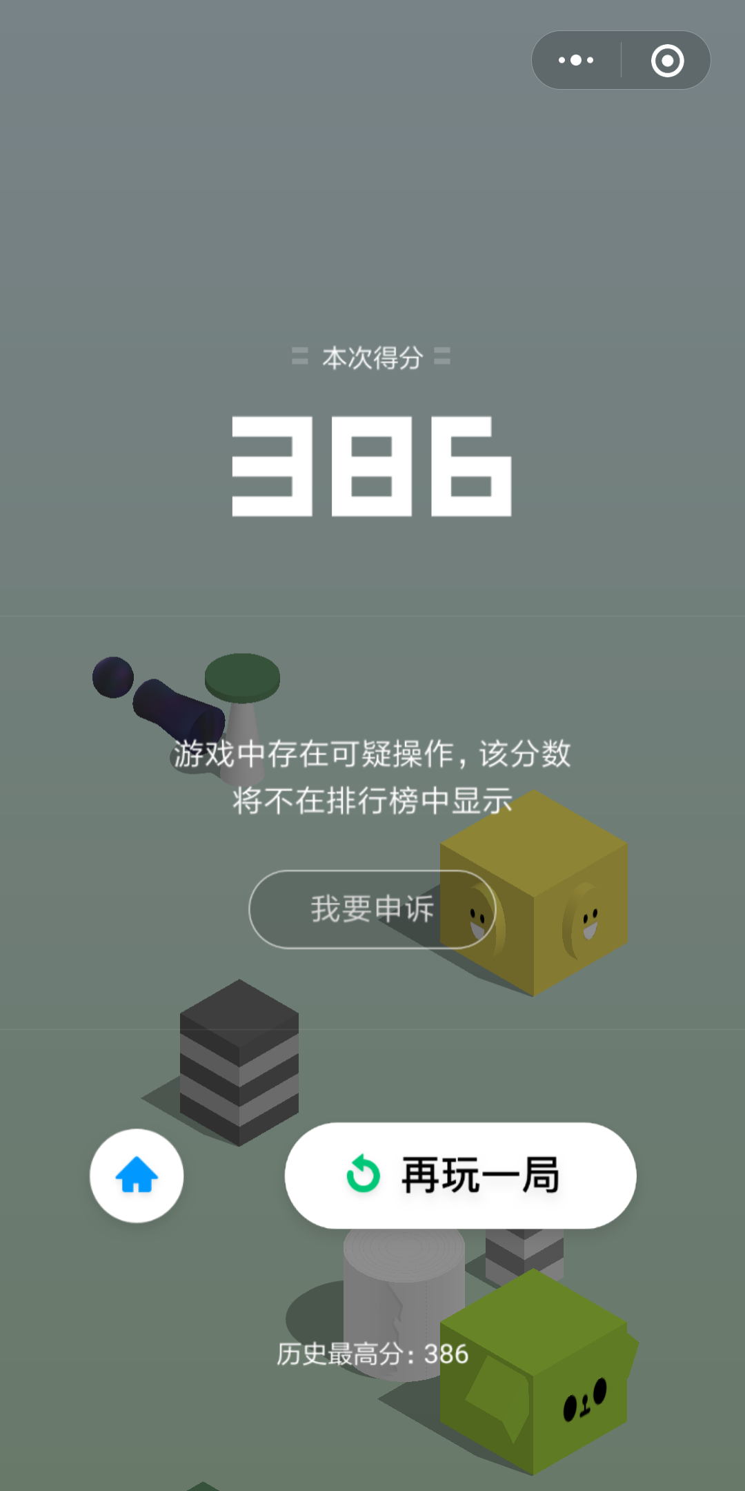
Oh Noes! We’ve Been Caught!
Everything’s working surprisingly well — too well. After having reached an acceptably high score and failing to reach a tiny platform, the game destroyed my excitement with the snarky message 《游戏中存在可疑操作,该分数将不在排行榜中显示》, informing me about suspicious activity and that my score won’t be displayed in the online leaderboard. 
I’ve had a quick think about this issue and brainstormed a few reasons that could have lead to the robot failing the Turing Test:
The game could be accessing motion sensors to determine if the phone is being held in a hand. In our case, the phone was stationary and there was no motion.
The robot always performs the tap at the same location. A human player is unlikely (to be able) to do that.
The touch pressure is always approximately the same, whereas a human touch would vary in strength.
The timing between the jumps was constant.
It might simply be too high of a score. Personally, I have never managed to achieve a score even close to what the robot can do. Also, more ‘realistic’ scores don’t seem to get flagged.
Going On a Tangent
I wanted to address all of the potential reasons above to try and get around the detection. To do that, I imagined the best way to achieve this is to repurpose an old acrylic 4DOF robot arm I had lying around.
To address the causes, I made these rather drastic changes:
I removed most of the arm and only kept the two servos that control pitch and yaw. I then duct-taped (of course) the rubber tip to the remaining part of the arm at a 90° angle. This allows me to not only move the tip up and down but also sway it across the screen to touch different (random) locations.
Place the phone on a box and attach a third servo it that will give the phone a little shake between turns.
Inject some randomness into code base: for each turn, move the tip to a new random position, wait a random period of time between turns, and vary the tap force slightly.
Here’s the result:
Ultimately, it didn’t seem to have much of an effect. Some of the scores would slip through (I still officially beat Nicole!), others wouldn’t, and I’m not sure what exactly causes this. Again, it might just be the score being too high. The changes, however, did severely increase the bot’s level of awesomeness.
What I’ve Learned
I’ve taken away a lot from this project as I’ve stepped into completely new territory. Not only was this first time for me to use an Arduino (although I had some lying around for a while), it was also the first time I looked into image analysis, object detection, and OpenCV in general.
What was interesting to me is that getting a “working” prototype up and running was relatively straightforward. What was extremely time consuming, however, was adjusting all the numerous parameters for OpenCV to make object detection more reliable and robust. Also, fine-tuning the jump timing (finding {$f$} and {$c$}) was an annoyance that repeated itself for every change of the setup.
This turned out to be much, much more frustrating than I anticipated. Especially because every time I had to move the setup — or accidentally bumped into the build — everything ever so slightly changed and had to be readjusted all over again. I truly learned the virtue of patience right there.
Overall, though, the project was incredibly fun to work on.